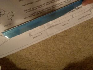
So far my riveting has gotten much better. I thought it was about time to try some of the more unique stuff, like back riveting, drilling countersinks, trailing edges, rolling and leading edges. One of my problems is I enjoy working too much, so I just breeze through it. This kit really forced me to slow down and read and understand the instructions, not just look at the pictures.
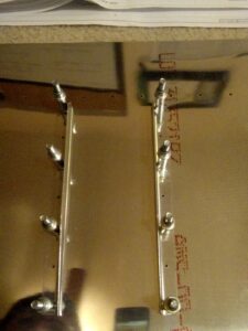
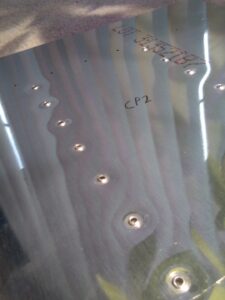
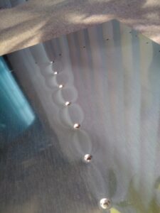
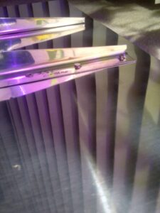
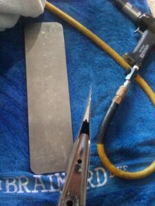
First step was to pull apart the ribs, trim, and debur. Then get them lined up with the skins and match drill and debur. Next we dimple the ribs and skins. I’ve wondered if the C-Frame, pneumatic, Vise-Grip, all produce the same quality dimples so I thought I’d try it. Each of the 4 ribs got a different method of dimpling (2 ribs were both pneumatic but with an ATS die and Avery die). I then checked the dimples and I couldn’t tell any difference within tolerance of operator error. The only result that I noticed slightly different was the Vise-Grip dimple, it consistently needed two squeezes to get the proper dimple. The pictures are below, see if you can notice a difference.
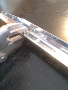
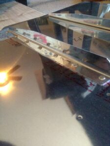
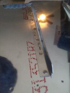
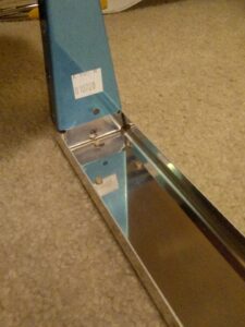
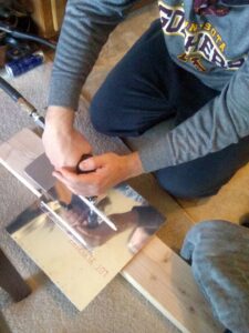
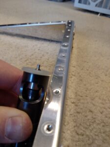
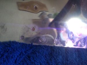
The next step was to add the end caps and dimple/countersink as necessary. Here you can also see how I’ve been doing the riveting in my apartment. I talked with my neighbors who live below me, and they said they didn’t notice anything really loud happening. So that’s good! But they also have a kid who does LOTS of screaming, so “loud” to them might be a little subjective. I got tired of doing a lot of dimpling with the pneumatic squeezer while trying to get everything level and lined up. So I made a little jig! Since some of the spar is a little thick to dimple, you dimple it the best you can then countersink the rest of the way. It took me a bit to get the depth set on the countersink cage, but once it’s set it’s set you can run through real quick.
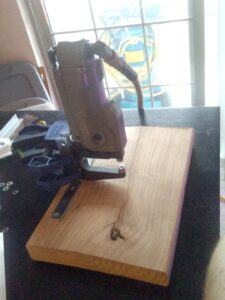
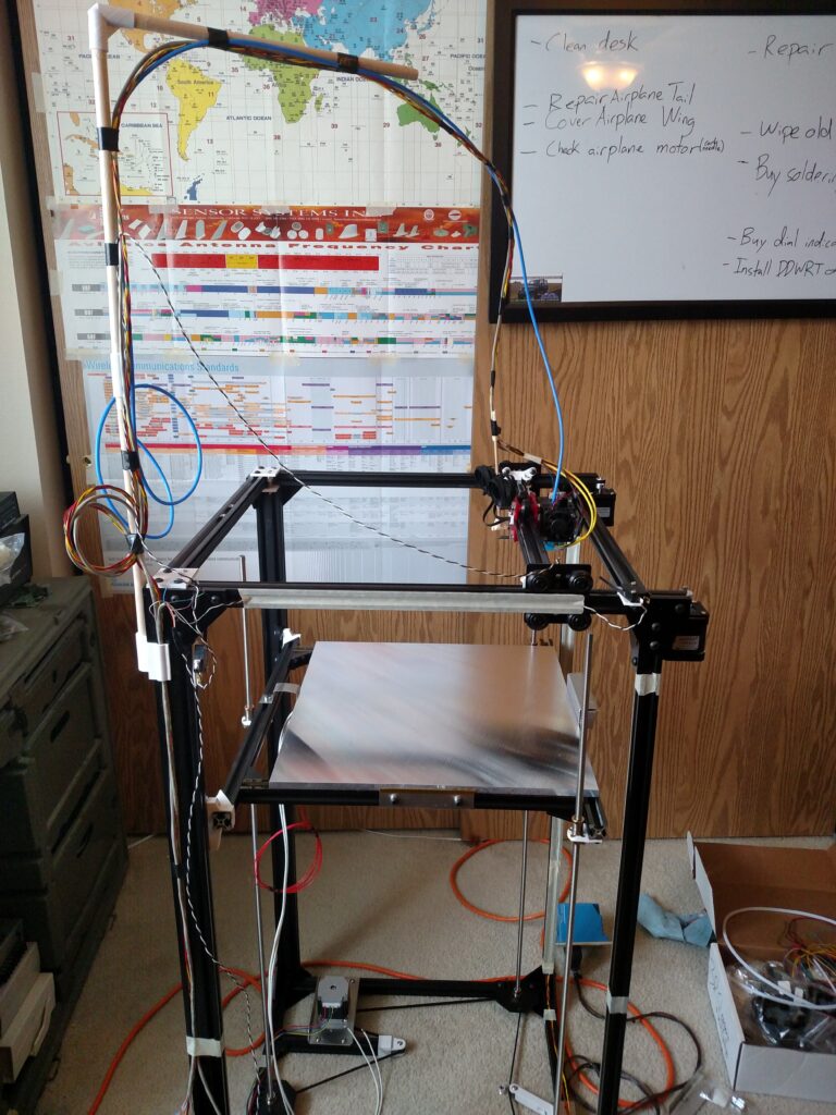
For a while now I’ve also been working on a 3D printer, I recently finished that and have been going through the tuning and testing process. Here’s a picture of that since I’m pretty proud of it. I’ve since added walls and cleaned up the wiring a bit. It can print almost all filaments and has a print area of 400x400x800mm.
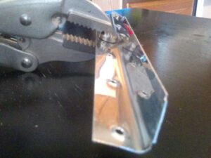
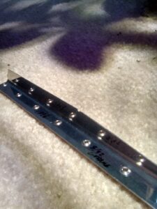
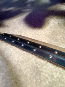
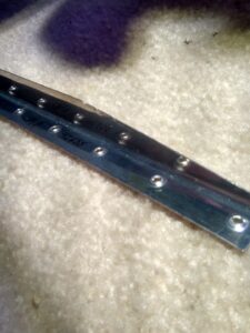
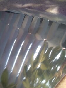
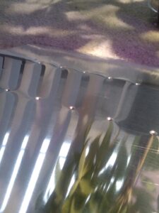
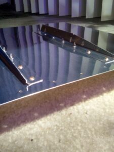
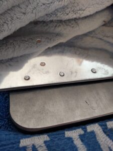
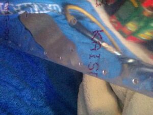
Back to the control surface. So the main parts are done, now it’s mostly assembly. I got the top and bottom skins put on and dimpled them with the wedge in between, see the picture below. The trailing edge turned out OK. You can see some points where I over riveted and expanded the skin causing it bulge.
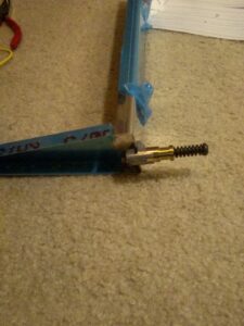
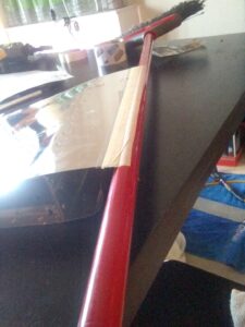
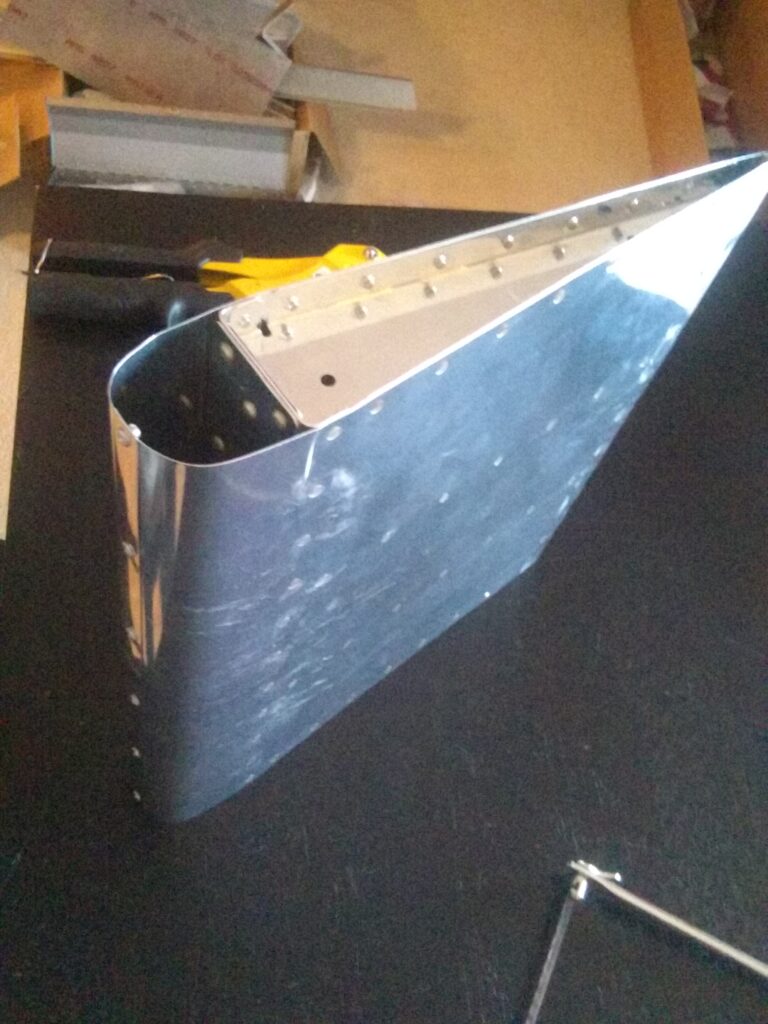
Final step was to do the leading edge. This is done by rolling the front of the skins over a pipe. Others have said they had good results with 1.5″-2″ PVC. I thought I’d try a broom since it’s what I had on hand. I taped one to the broom and rolled it on the table to start the curve. I kept going slowing increasing the force on the broom tightening the curve. After getting a nice 90 degree bend I went on to the next one. I rolled it out until I got a little more than a 90 degree bend, like a 100. This is done so the two skins naturally press into each-other, relieving some of the tension on the rivet and strengthening the joint.
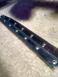
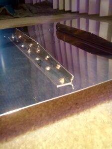
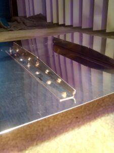
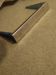
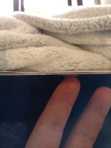
Overall it actually turned out pretty well! A little asymmetric, but with a little massaging it worked out. My only complaint was the leading skin had a bit of tension diagonally. I’m not sure what caused this, and you can kind of tell in the last picture as there is a little remaining asymmetry. I started by drilling the two ends, then cleco’ing and doing the middle and so on. I would imagine doing the real control surface would be easier to square because of it’s length.
I spent 5 hours working on this.
Leave a Reply