General Updates
-
Garage Workshop
After moving out of the apartment and into the house, most of my things got put into the garage and basement. So I’ve been spending a fair amount of time organizing and rearranging. After finishing the workbench I finally had time to move into the garage and get to work putting in shelving and unpacking…
-
First kits purchased!
Well I took the plunge! The Empennage and Wing Kit were ordered! The Empennage had 4 month lead time and the Wing Kit 7. I’ve heard the Empennage can be done in a month or two so I wanted to order them at the same time. Then the question was two separate orders or one.…
Latest Updates
-
The Big Move to California
Some Background
As some may know, I’m an Air Traffic Controller for the Gov. My first assignment was the tower/TRACON at Cedar Rapids, IA. After a few years I decided I was ready for something larger and more challenging. The transfer process is, well… a bit complicated. The short version is the facility you’re at has to have enough people that it can be fully staffed without you and the facility you want to go to has to be below fully staffed. I was trying to go to a few different facilities; AUS, NCT, OKC, OMA, PHX, and R90. Well 5 years after arriving at CID, I was selected for NorCal (Northern California) TRACON in Sacramento, CA. The selection happened in September and my report date was mid-January. I spent the next few months going through boxes of stuff and old electronics I’ve collected over the years. My goal was to finish at least the tail of the plane but it became apparent pretty quick that rushing was going to lead to mistakes, poor quality, and an end result I wasn’t happy with. So back into the crates everything went!
Moving
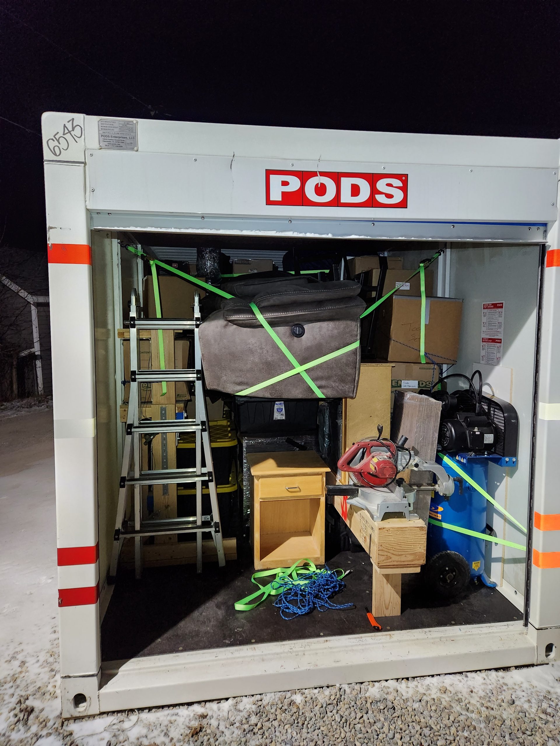
After pricing out my options, looking at when I’d have help, and making a pro/con list; I decided I would use PODs. The largest they have is 16′, the wing spar crate is 15’6″. So I knew it would be close! Worst case I would put the spar crate in diagonally on one side, and use 2x4s to hold it in place. Mid-December came and the POD was delivered. I measured and my gosh the crate was going to fit! I had the POD packed full and I was honestly worried it would be overweight and I would have only a few days to rearrange or get rid of more stuff and repack. See some of the pictures below. The whole process, from the planning, the packing, the moving, the unpacking… Working airplanes doesn’t stress me out as much as that whole process did!
Current Plans
So I’m sure you’re wondering what the plan is going forwards. Well as of writing this (Mar ’23) it’s indefinitely paused. ATC training is no joke. It takes a heck of a lot out of you mentally and requires a significant amount of time outside of work studying. I’m using the airplane project as motivation to work hard and try and be successful in training. When I’m done training I’ll start on it again. Training will likely take from one year to two years. Until then, I’ve got many other small projects to work on to keep me busy.

The POD almost fully packed in Iowa 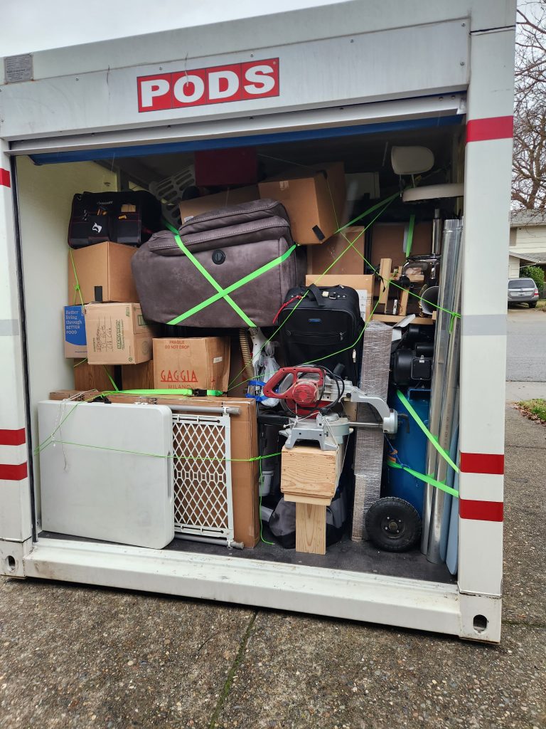
The POD as it arrived in CA 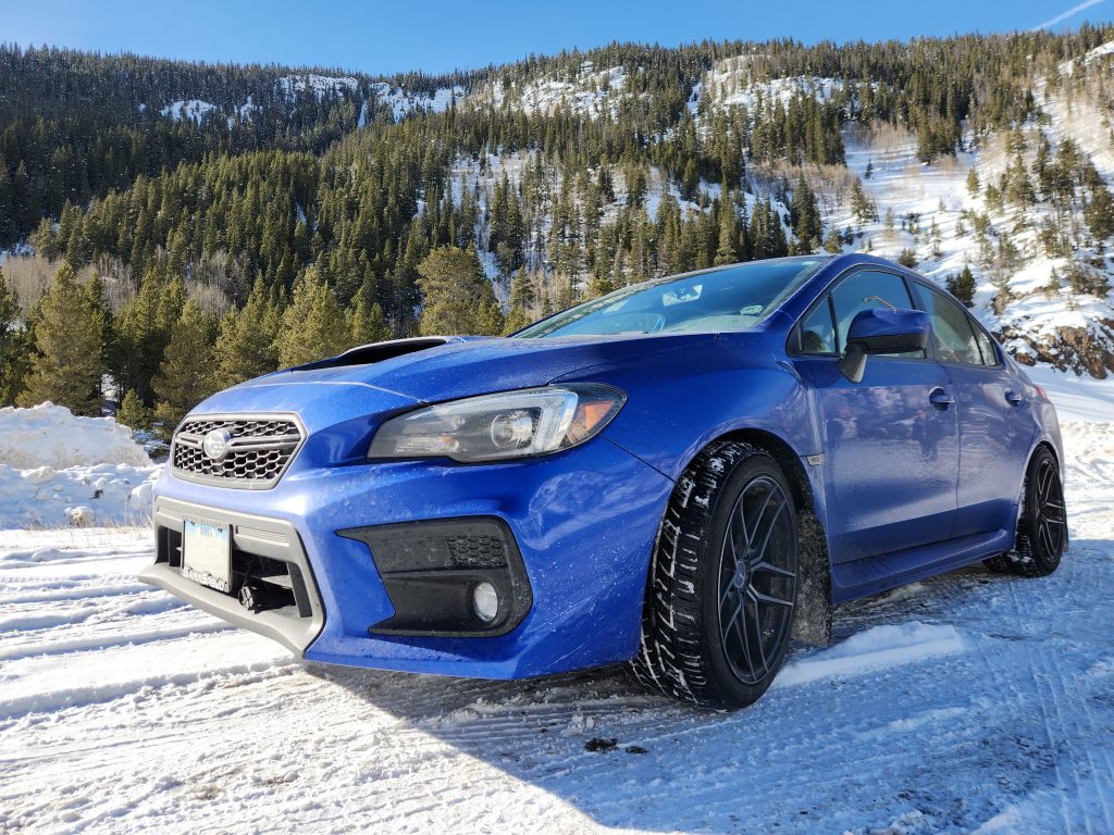
Had to get a Subaru pic! 
Sunset coming out of the Donner Pass 
The emptiness of Utah 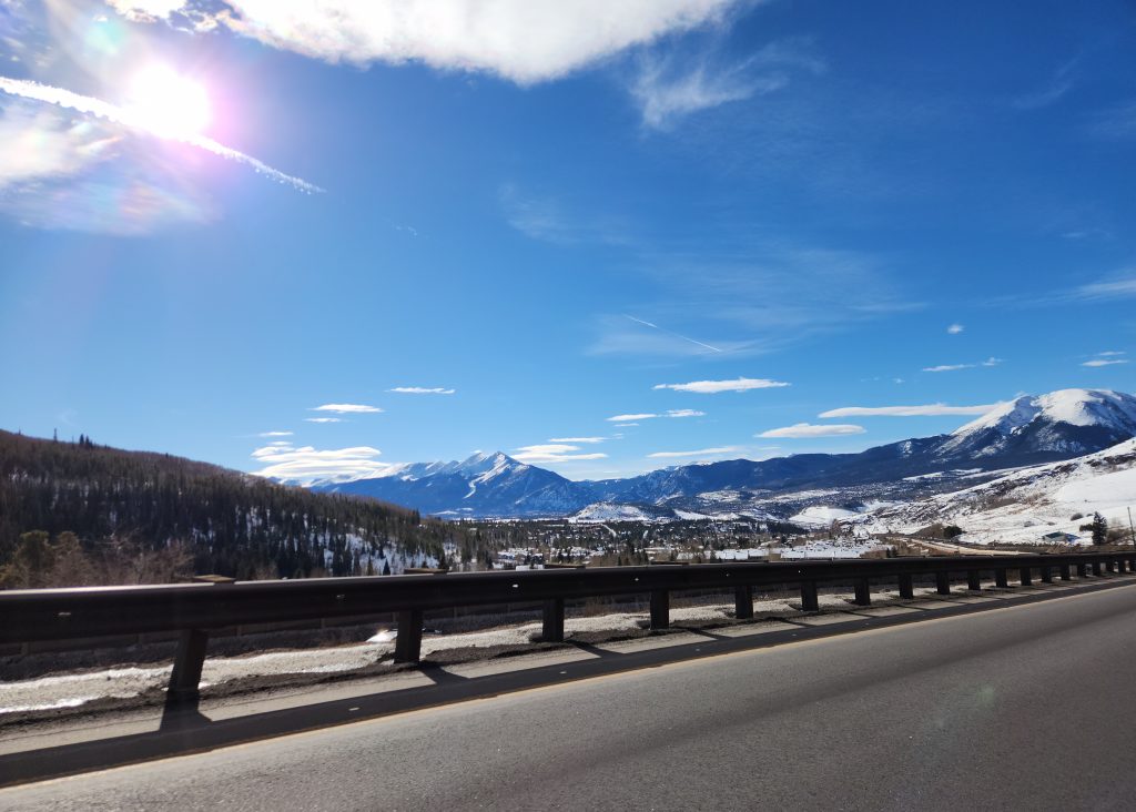
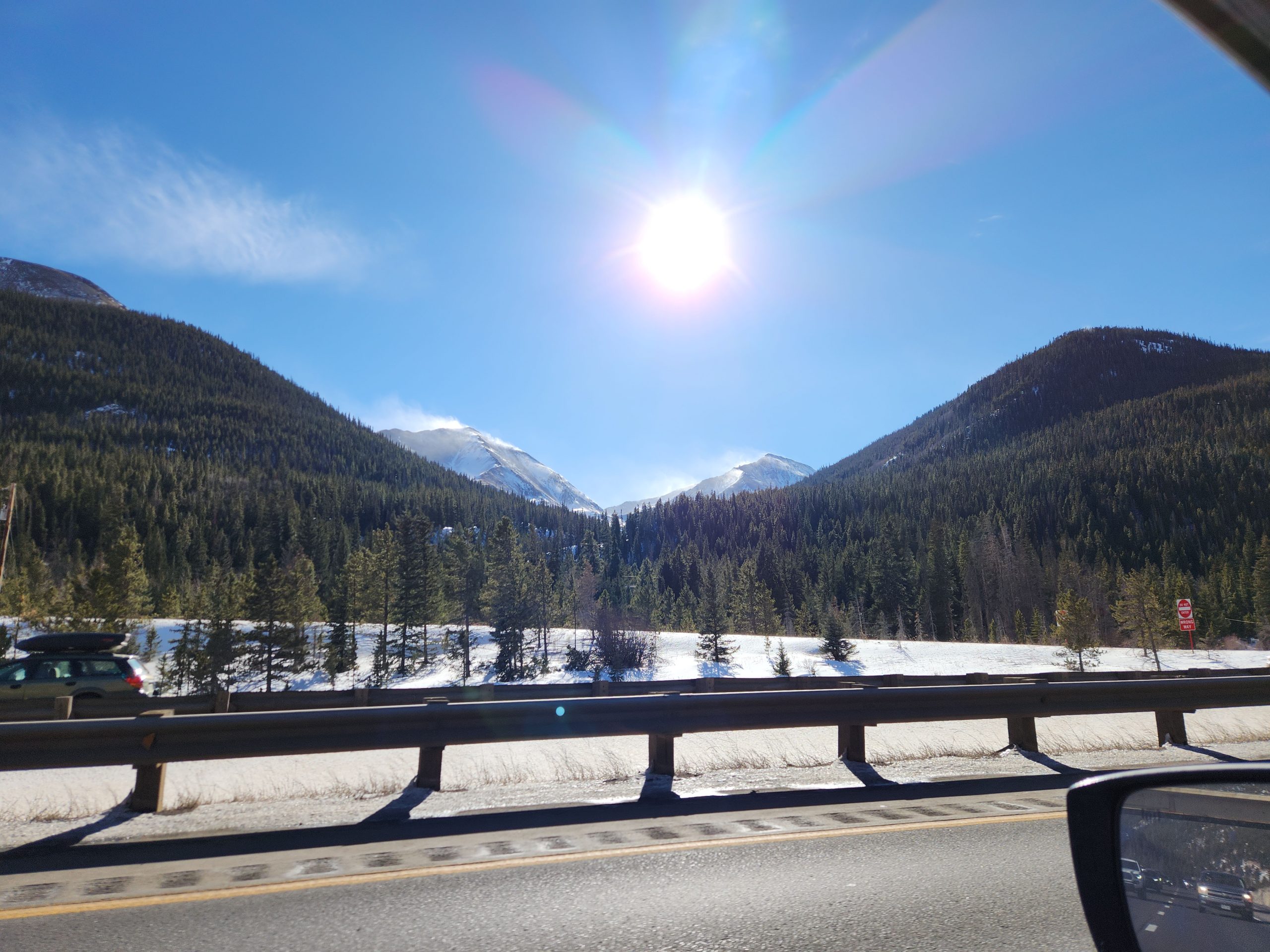
Somewhere around Denver 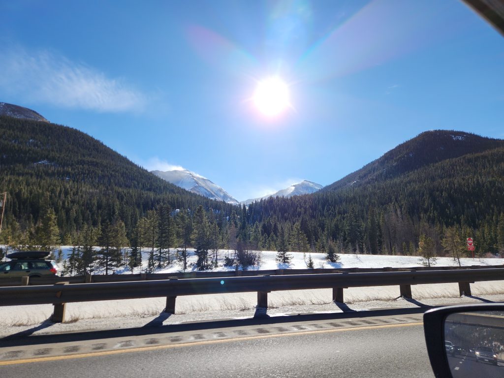
Somewhere near Denver -
First actual build day!
After a early and long day at work, it felt good to come back home and relax a bit. I had been looking at the plans and drawings for a while, reading through trying to figure out exactly how I wanted to go about it. Eventually you have to jump in. No matter how much research I did, I probably would never have felt ready. Thanks to the girlfriend for giving me the push and encouragement to get started.
Horizontal Stabilizer
The instructions tell you to start with the rear spar assembly. Break the edges of the rear spar reinforcement bars, and shaving the edges so it lays flat inside the rear spar channel. After doing this, rounding the ends, and wet sanding with 400 then 600 grit to remove all milling marks and making it nice and smooth. I decided that maybe the large Horizontal Stabilizer isn’t what I should start with. This isn’t uncommon, after reading some advice on vansairforce a few builders recommend starting with the Vertical Stabilizer. That way if you screw something up it’s smaller and cheaper to replace.

after rounding and before wet sanding 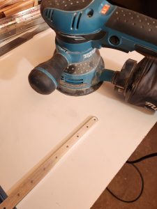
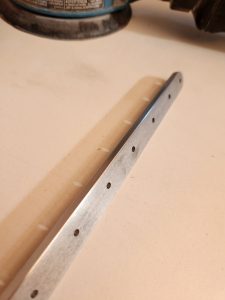
the nice sheen after wet sanding Vertical Stabilizer
I put the Horizontal parts away and pulled out the Vertical ones needed. As far as structure there really isn’t much, so it’s coming together quickly! I forgot my phone in the house so all you get is one picture of the doubler and lower hinge.
I spent 2.5 hours working on this, and logged it as Horizontal Stabilizer since that’s where most of my time went.
-
Moving and Building a Workbench
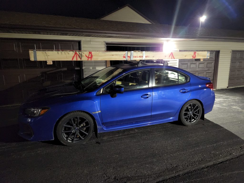
After finishing the inventory of the wing kit I started bringing things from the apartment to the house I was starting to rent. Most of the parts are pretty small and easy to transport, but obviously the spars and longerons are a bit long. What better way to transport them than on top of the Subaru!
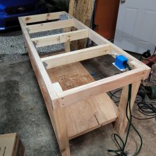
Building of the workbench
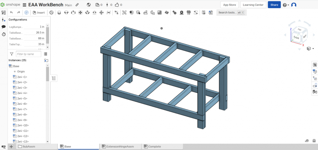
The EAA 1000 workbench is a standard shop item. They are easy to build, customize and fairly cheap. To help me decide the dimensions and how I wanted it all to look and work, I modeled it in CAD with onshape.
My girlfriend wanted to have a date night, so I decided I’d have her help me build the workbench.
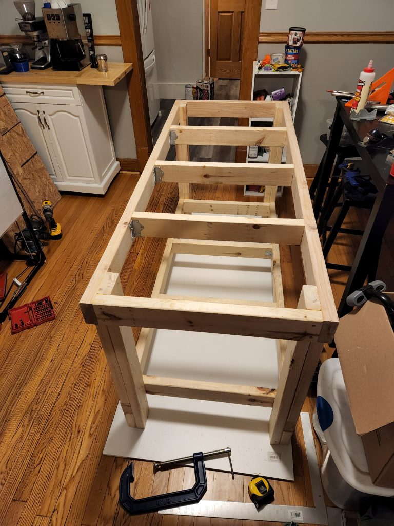
I’m using the tabletop as a base to make sure everything is flat and level. 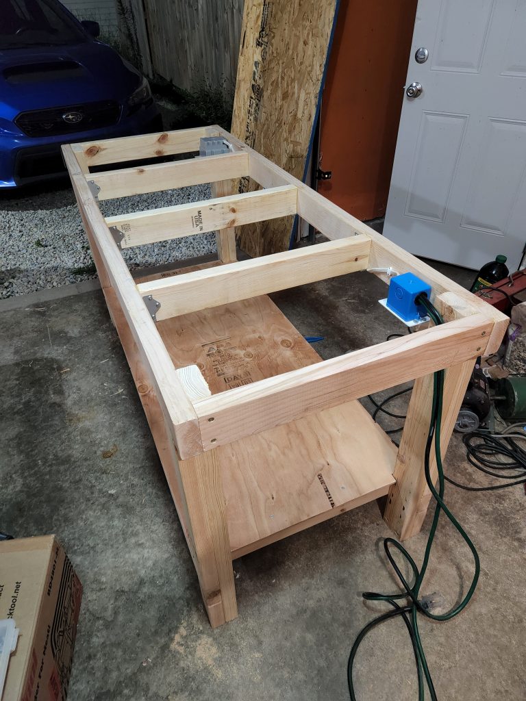
Here the base is installed and electrical is ran. It turned out pretty good. About $100 in supplies and much of the plywood was reused from the shipping crates. I also added a half-shelf on one side of the bench. Below are the completed pictures as well as how the garage is laid out. Note how much of the crates I’ve reused for shelving and storage.
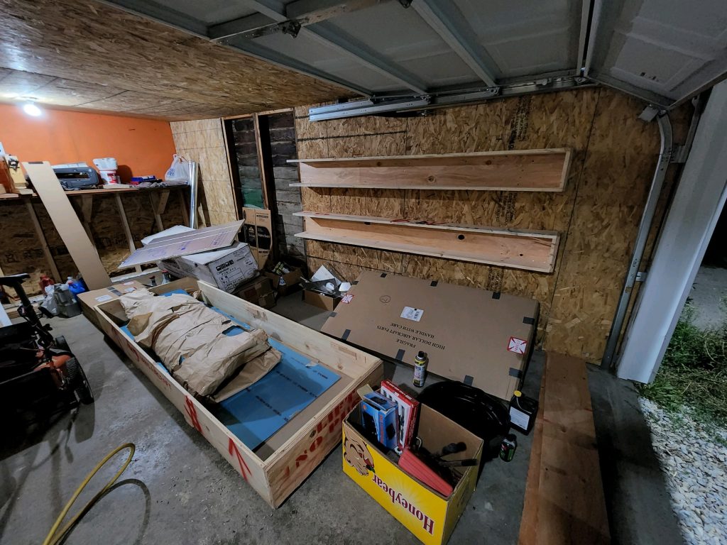
That’s the two halves of the longeron crate on the wall. 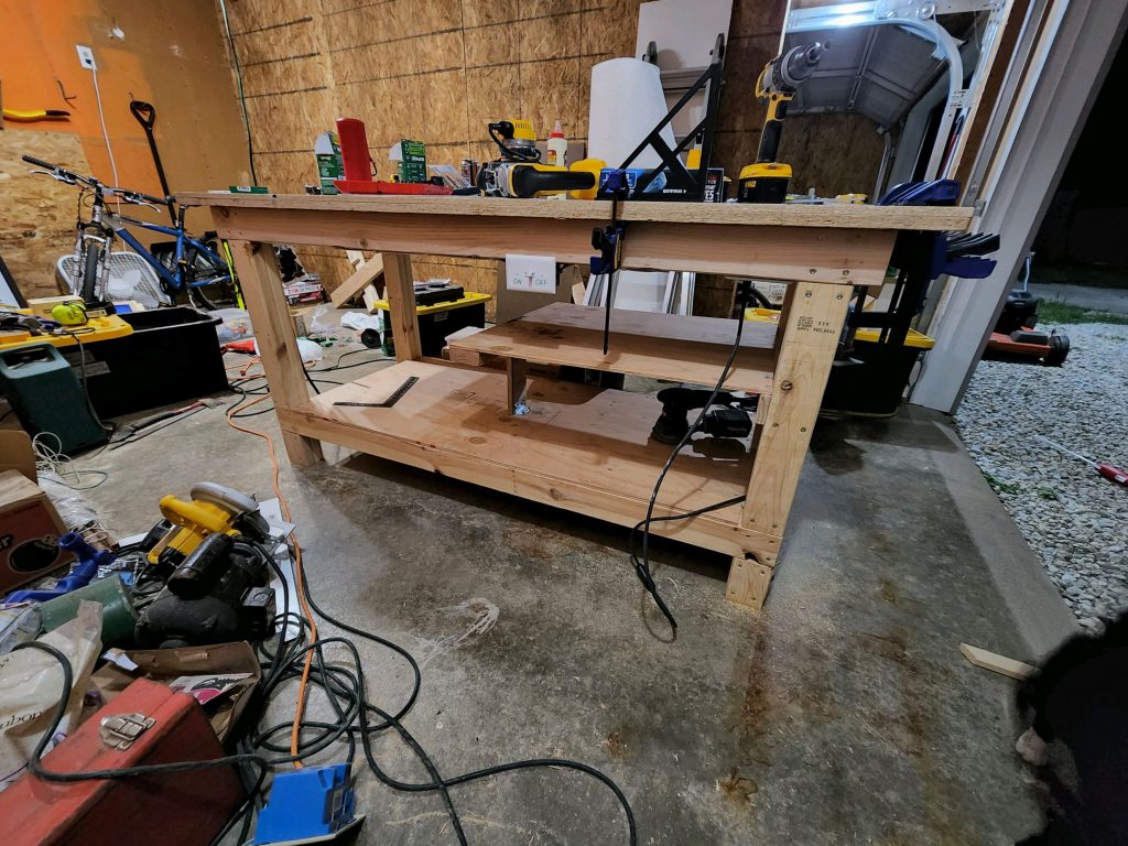
Here you can see the half-shelf 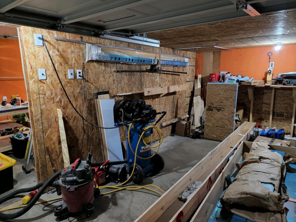
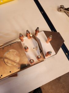
Some large L-brackets are bearing most of the weight of the spars.